1 / 1
 Wenda Electronics
Terminal Details: T = 0.2mm
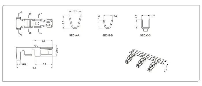
| Part No. | Wire Range | Insulation O.D | Material | Finish |
|---|---|---|---|---|
| WT200R0-T0 | AWG #28 ~ #22 | 1.50mm MAX | Phosphor bronze | Tin & Gold-plated |
Material: Nylon 66 UL94V-0
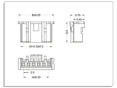
| CKT | Part No | DIM A | DIM B |
|---|---|---|---|
| 2 | WT200R0-02 | 2 | 6 |
| 3 | WT200R0-03 | 4 | 8 |
| 4 | WT200R0-04 | 6 | 10 |
| 5 | WT200R0-05 | 8 | 12 |
| 6 | WT200R0-06 | 10 | 14 |
| 7 | WT200R0-07 | 12 | 16 |
| 8 | WT200R0-08 | 14 | 18 |
| 9 | WT200R0-09 | 16 | 20 |
| 10 | WT200R0-10 | 18 | 22 |
| 11 | WT200R0-11 | 20 | 24 |
| 12 | WT200R0-12 | 22 | 26 |
| - | - | - | - |
| 16 | WT200R0-16 | 30 | 34 |
Material and Finish: Housing: PA6T UL 94V-0 & Terminal: Brass Fitting: Brass; Finish: Tin-plated & Gold-plated
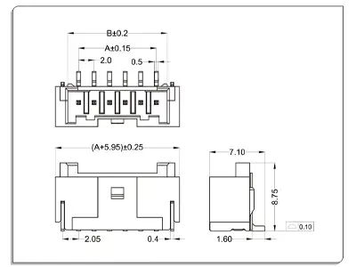
| CKT | Part No | DIM A | DIM B |
|---|---|---|---|
| 2 | WT200RL-02 | 2 | 4.75 |
| 3 | WT200RL-03 | 4 | 6.75 |
| 4 | WT200RL-04 | 6 | 8.75 |
| 5 | WT200RL-05 | 8 | 10.75 |
| 6 | WT200RL-06 | 10 | 12.75 |
| 7 | WT200RL-07 | 12 | 14.75 |
| 8 | WT200RL-08 | 14 | 16.75 |
| 9 | WT200RL-09 | 16 | 18.75 |
| 10 | WT200RL-10 | 18 | 20.75 |
| 11 | WT200RL-11 | 20 | 22.75 |
| 12 | WT200RL-12 | 22 | 24.75 |
| - | - | - | - |
| 16 | WT200RL-16 | 30 | 32.75 |
Material and Finish: Housing: PA6T UL 94V-0 & Terminal: Brass Fitting: Brass; Finish: Tin-plated & Gold-plated
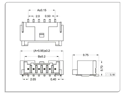
| CKT | Part No | DIM A | DIM B |
|---|---|---|---|
| 2 | WT200RW-02 | 2 | 4.75 |
| 3 | WT200RW-03 | 4 | 6.75 |
| 4 | WT200RW-04 | 6 | 8.75 |
| 5 | WT200RW-05 | 8 | 10.75 |
| 6 | WT200RW-06 | 10 | 12.75 |
| 7 | WT200RW-07 | 12 | 14.75 |
| 8 | WT200RW-08 | 14 | 16.75 |
| 9 | WT200RW-09 | 16 | 18.75 |
| 10 | WT200RW-10 | 18 | 20.75 |
| 11 | WT200RW-11 | 20 | 22.75 |
| 12 | WT200RW-12 | 22 | 24.75 |
| - | - | - | - |
| 16 | WT200RW-16 | 30 | 32.75 |
Material: Nylon 66 UL94V-0
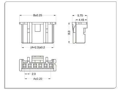
| CKT | Part No | DIM A | DIM B |
|---|---|---|---|
| 2 | WT200R0-02 | 2 | 6 |
| 3 | WT200R0-03 | 4 | 8 |
| 4 | WT200R0-04 | 6 | 10 |
| 5 | WT200R0-05 | 8 | 12 |
| 6 | WT200R0-06 | 10 | 14 |
| 7 | WT200R0-07 | 12 | 16 |
| 8 | WT200R0-08 | 14 | 18 |
| 9 | WT200R0-09 | 16 | 20 |
| 10 | WT200R0-10 | 18 | 22 |
| 11 | WT200R0-11 | 20 | 24 |
| 12 | WT200R0-12 | 22 | 26 |
| - | - | - | - |
| 16 | WT200R0-16 | 30 | 34 |
Material and Finish: Housing: Nylon 66 UL 94V-0 & Terminal: Brass; Finish: Tin-plated & Gold-plated
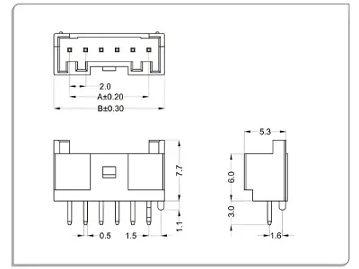
| CKT | Part No | DIM A | DIM B |
|---|---|---|---|
| 2 | WT200RL-02 | 2 | 6 |
| 3 | WT200RL-03 | 4 | 8 |
| 4 | WT200RL-04 | 6 | 10 |
| 5 | WT200RL-05 | 8 | 12 |
| 6 | WT200RL-06 | 10 | 14 |
| 7 | WT200RL-07 | 12 | 16 |
| 8 | WT200RL-08 | 14 | 18 |
| 9 | WT200RL-09 | 16 | 20 |
| 10 | WT200RL-10 | 18 | 22 |
| 11 | WT200RL-11 | 20 | 24 |
| 12 | WT200RL-12 | 22 | 26 |
| - | - | - | - |
| 18 | WT200RL-18 | 34 | 38 |
Material and Finish: Housing: Nylon 66 UL 94V-0 & Terminal: Brass; Finish: Tin-plated & Gold-plated
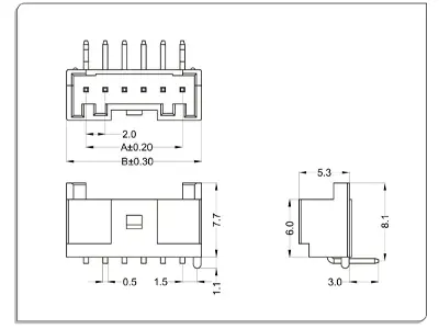
| CKT | Part No | DIM A | DIM B |
|---|---|---|---|
| 2 | WT200RW-02 | 2 | 6 |
| 3 | WT200RW-03 | 4 | 8 |
| 4 | WT200RW-04 | 6 | 10 |
| 5 | WT200RW-05 | 8 | 12 |
| 6 | WT200RW-06 | 10 | 14 |
| 7 | WT200RW-07 | 12 | 16 |
| 8 | WT200RW-08 | 14 | 18 |
| 9 | WT200RW-09 | 16 | 20 |
| 10 | WT200RW-10 | 18 | 22 |
| 11 | WT200RW-11 | 20 | 24 |
| 12 | WT200RW-12 | 22 | 26 |
| - | - | - | - |
| 18 | WT200RW-18 | 34 | 38 |
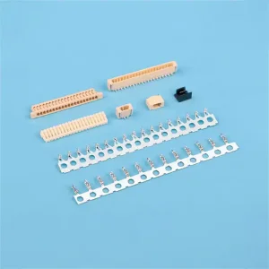
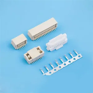
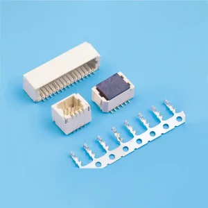
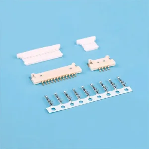
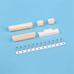
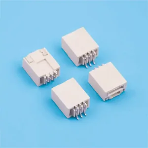
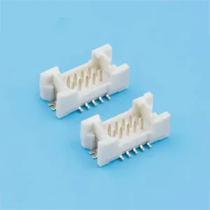
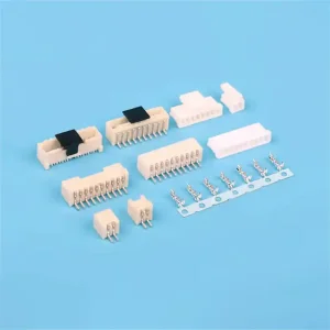
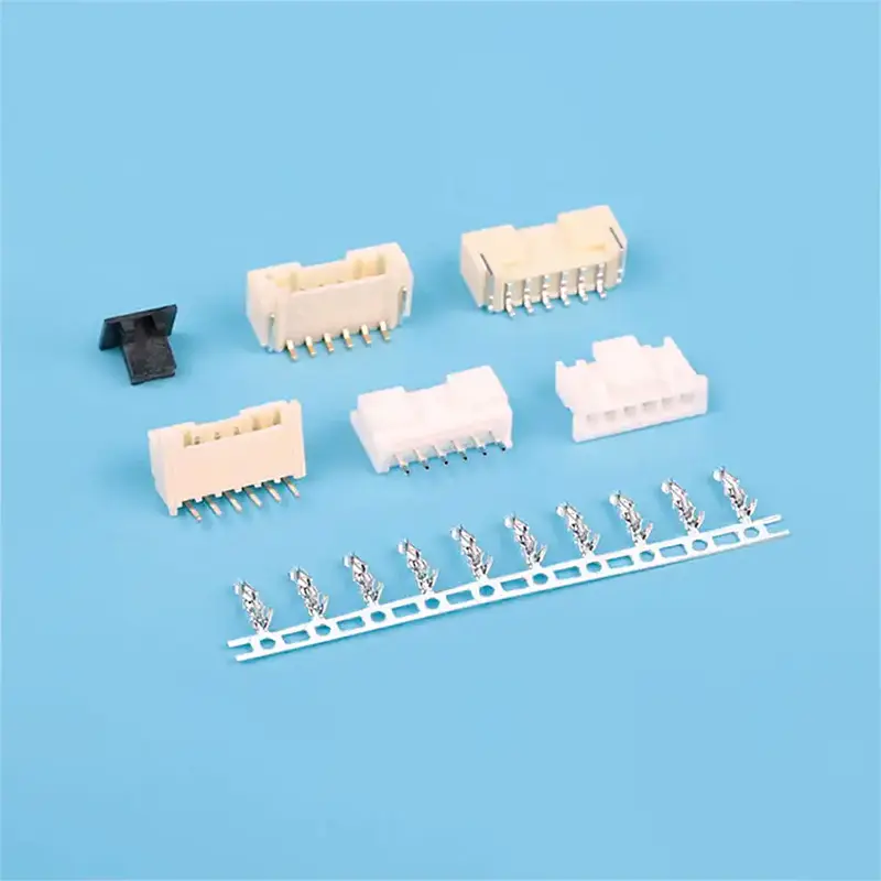
The WT200 series wire-to-board connectors are highly versatile, offering configurations ranging from 2Pin to 18Pin depending on the specific model and material choice selected for your application.
These connectors support a maximum current rating of 3A AC/DC and a maximum voltage rating of 250V AC/DC, making them optimized for standard low-power and signal distribution systems.
The housings are manufactured using high-quality Nylon 66 UL94V-0 or PA6T UL94V-0. Wafers feature robust brass terminals with advanced tin-plated and gold-plated finish options to prevent oxidation and ensure reliable conductivity.
The WT200 series accommodates applicable wires ranging from AWG #28 to #22 and is engineered for use with standard PCB thicknesses between 1.6mm and 2.0mm.
The operating temperature range is -25°C to +85°C, designed to withstand standard thermal load and ambient environments. This includes the internal temperature rise generated when electrical current is applied.